555 pwm dc motor controller circuit Wiring diagram of motor control Pwm motor dc controller circuit ne555 diagram transistors darlington 555 dimmer led power using transistor voltage generator switch battery eleccircuit circle diagram for motor
3 Phase Motor Control Circuit Diagram | Rig Electrician Training - YouTube
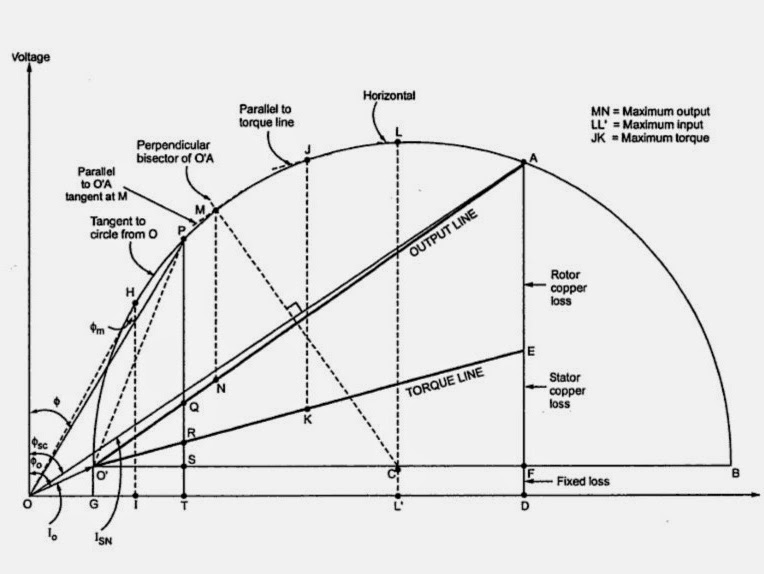
Circle diagram power motor induction maximum quantities electrical4u line output Circle diagram of the induction motor Diagram circle motor simplified rotor resistance fig low
Motor diagram asynchronous circle english writework dahlander
Forward & reverse 3 phase ac motor control circuit diagramEngine simple engines camshaft overhead burbank Lecture 4 circle diagram in induction motor by prof h j bhakharThe simplified circle diagram.
Circle diagram of induction motorCircle diagram of induction motor Scheme electric motor[diagram] electric motor internal wiring diagrams.

Kbreee: circle diagram of induction motor
3 phase motor wiring diagramsMotor circle diagram Motor circuit phase diagram control rigForward motor phase ac reverse control diagram circuit electrical.
12v 30a pwm circuit diagramDahlander motor Circle diagram archivesMotor timing on/off control circuit diagram.

Dc motor: what is it? how does it work? types, uses
Circle diagram of induction motorMotor circle diagram – geogebra 3 phase motor control circuit diagramPhase motor wiring diagrams diagram electrical control motors circuit delta connection engineering star stop power panel non transition chapter open.
Simple diagram of a car : car engines types| rapid-racer.com. : it canMotor circle diagram – geogebra Motor diagram induction circle point electrical obtained parameters discussed easily known once performance above other.


![[DIAGRAM] Electric Motor Internal Wiring Diagrams - MYDIAGRAM.ONLINE](https://i2.wp.com/electrical-engineering-portal.com/wp-content/uploads/2016/12/motor-circuit-diagram-1-pole-3-pole.png)