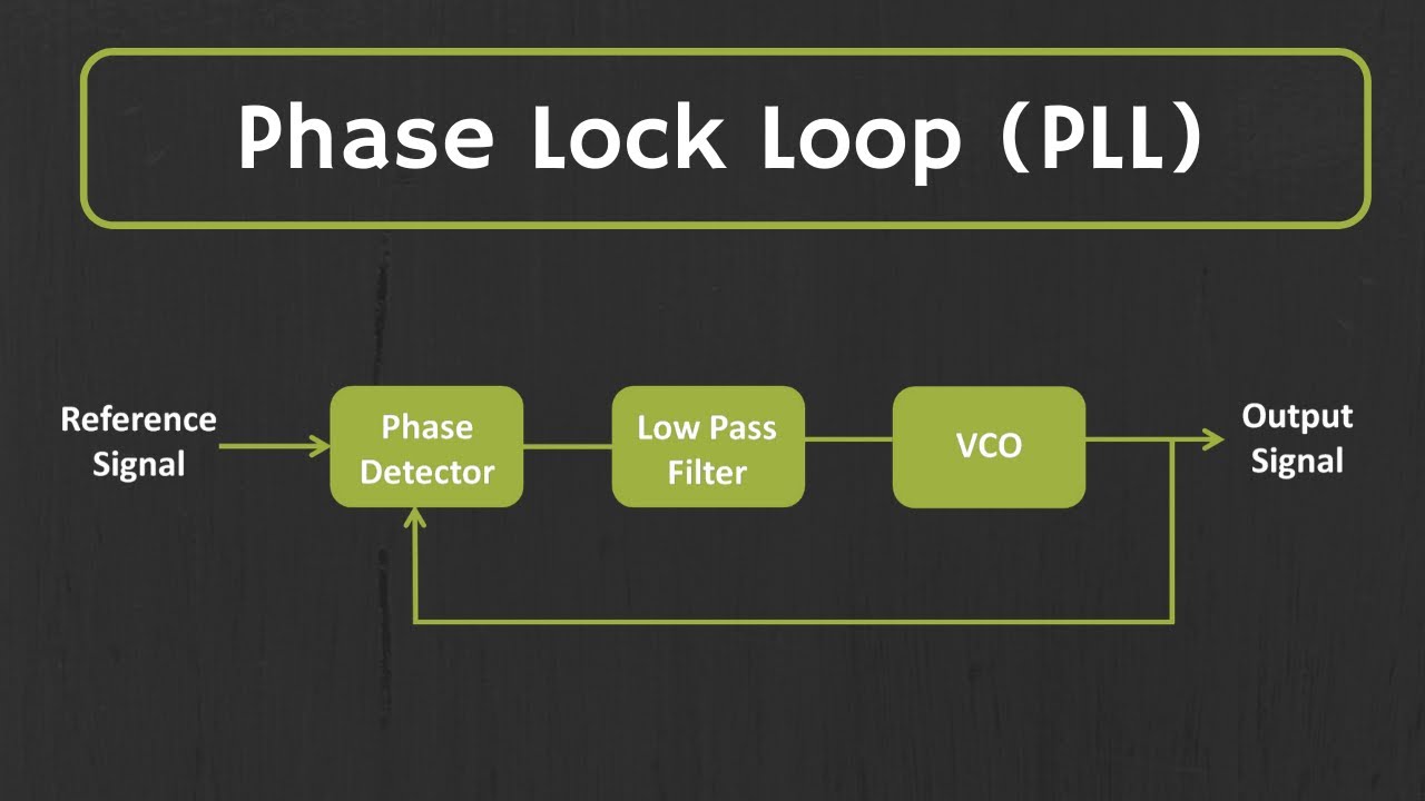
(a) phase locked loop (pll) circuit; (b) characteristics of the pll Pll loop phase locked diagram block electrical electronic engineering frequency 5g mmwave signal chain: the phase-locked loop circuit diagram for of pll used for phase angle measurement
Schematic diagram of the PLL simulation circuit | Download Scientific
Pll locked How to measure phase angles with a phase angle meter • valence Phase-locked loop (pll) fundamentals
Full-band phase locked loop circuit diagram fast under pll circuits
Phase locked loop principle at laura addy blogPll locked analog detector fundamentals Block diagram of the pll circuit and set-up for linewidth measurementPhase-locked loop (pll) fundamentals.
Pll locked analog block fundamentals modulus vco divider prescaler detectorPll vco loop Phase capturing of pll.Basic phase angle measurement circuitry..

Three phase pll circuit and generation of reference signal
Phase angle differencePhase-locked loop tutorial, pll Measurement angle circuitryPll phase loop locked fundamentals.
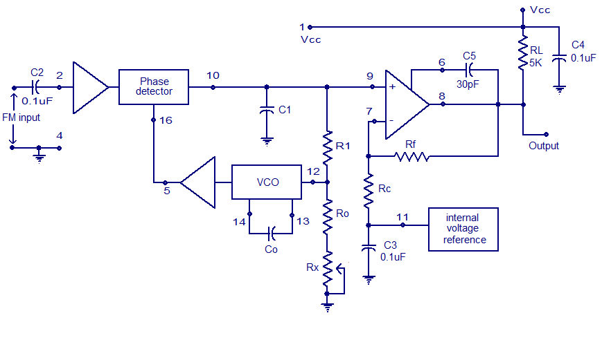
Pll circuit diagram pdfPhase-locked loop (pll) fundamentals Phase angle meter measure angles electrical ac circuit would next measurement measurementsXr2212 pll fm demodulator circuit |free electronic circuit diagrams.

How does a pll circuit work
Phase-locked loop (pll) fundamentalsElectrical and electronic engineering: phase locked loop (pll) The structure of the pll based control circuitPll signal implementation enhanced.
Estimation of grid phase angle at steady state with proposed pllPhase detector circuit diagram Shows the schematic diagram of the pll circuit for tracking frequencyPll phase loop locked detector frequency fundamentals.

Pll circuit block diagram and working
Demodulator pll ic circuits workingPhase angle with pll Pll loop phase locked filter vco analog source feedback faq model pd devices mt figure parts mainPhase locked loop ic.
Phase angle waves wave current electrical between amplitude different difference voltage time potential sweeping period relationship resistance wavelength reactance directionPhase-locked loop (pll) fundamentals Faq: what is phase locked loop (pll)?Detector circuit phase pll.

Pll schematic diagram
Pll schematic diagramSchematic diagram of the pll simulation circuit Three-phase pll control diagram.Pll circuit diagram.
.